Product Description
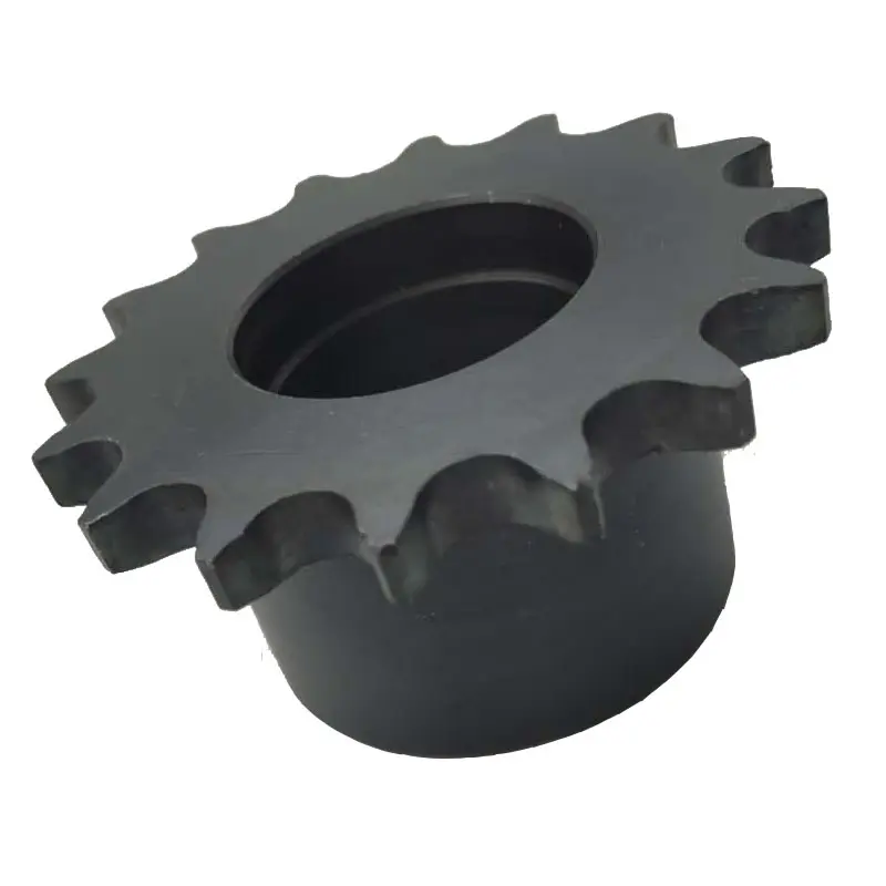
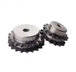
Stainless Steel Plastic Roller Chain Gear Platewheel Engineer Class Agricultural Pintle Cast Iron Weld On Hub Finished Bore Idler Bushing Taper Lock Qd Sprocket
|
European standard sprockets |
|
|
DIN stock bore sprockets & plateheels |
03B-1 04B-1 05B-1-2 06B-1-2-3 081B-1 083B-1/084B-1 085B-1 086B-1 08B-1-2-3 10B-1-2-3 12B-1-2-3 16B-1-2-3 20B-1-2-3 24B-1-2-3 |
|
03A-1 04A-1 05A-1-2 06A-1-2-3 081A-1 083A-1/084A-1 085A-1 086A-1 08A-1-2-3 10A-1-2-3 12A-1-2-3 16A-1-2-3 20A-1-2-3 24A-1-2-3 |
|
|
DIN finished bore sprockets |
06B-1 08B-1 10B-1 12B-1 16B-1 20B-1 |
|
stainless steel sprockets |
06B-1 08B-1 10B-1 12B-1 16B-1 |
|
taper bore sprockets |
3/8″×7/32″ 1/2″×5/16″ 5/8″×3/8″ 3/4″×7/16″ 1″×17.02mm 1 1/4″×3/4″ |
|
cast iron sprockets |
06B-1-2-3 081B-1 083B-1/084B-1 085B-1 086B-1 08B-1-2-3 10B-1-2-3 12B-1-2-3 16B-1-2-3 20B-1-2-3 24B-1-2-3 |
|
platewheels for conveyor chain |
20×16mm 30×17.02mm P50 P75 P100 |
|
table top wheels |
P38.1 |
|
idler sprockets with ball bearing |
8×1/8″ 3/8″×7/32″ 1/2″×1/8″ 1/2″×3/16″ 1/2″×5/16″ 5/8″×3/8″ 5/8″×3/8″ 5/8″×3/8″ 3/4″×7/16″ 3/4″×7/16″ 1″×17.02mm 1 1/4″×3/4″ |
|
double simplex sprockets |
06B-1 08B-1 10B-1 12B-1 16B-1 |
|
American standard sprockets |
|
|
ASA stock bore sprockets |
-2 35-3 -2 40-3 50 50-2-50-3 60 60-2 60-3 80-80-2 80-3 100 100-2 100-3 120 120-2 120-3 140 140-2 160 160-2 180 200 |
|
finished bore sprockets |
|
|
stainless steel sprockets |
60 |
|
double single sprockets&single type Csprockets |
|
|
taper bore sprockets |
35 35-2 -2 50 50-2 60 60-2 80 80-2 |
|
double pitch sprockets |
2040/2042 2050/2052 2060/2062 2080/2082 |
|
sprockets with split taper bushings |
40-2 40-3 50 50-2 50-3 60 60-2 60-3 80 80-2 80-3 100 100-2 120 120-2 |
|
sprockets with QD bushings |
35 35-1 35-2 -2 40-3 50 50-2 50-3 60 60-2 60-3 80 80-2 80-3 100 100-2 100-3 |
|
Japan standard sprockets |
|
|
JIS stock sprockets |
140 160 |
|
finished bore sprockets |
FB25B FB35B FB40B FB50B FB60B FB80B FB100B FB120B |
|
double single sprockets |
40SD 50SD 60SD 80SD 100SD |
|
double pitch sprockets |
|
|
speed-ratio sprockets |
C3B9N C3B10N C4B10N C4B11 C4B12 C5B10N C5B11 C5B12N C6B10N C6B11 C6B12 |
|
idler sprockets |
35BB20H 40BB17H 40BB18H 50BB15H 50BB17H 60BB13H 60BB15H 80BB12H |
|
table top sprockets |
P38.1 |
|
Material available |
Low carbon steel, C45, 20CrMnTi, 42CrMo, 40Cr, stainless steel. Can be adapted regarding customer requirements. |
|
Surface treatment |
Blacking, galvanization, chroming, electrophoresis, color painting, … |
|
Heat treatment |
High frequency quenching heat treatment, hardened teeth, carbonizing, nitride, … |
Customization process
1.Provide documentation:CAD, DWG, DXF, PDF,3D model ,STEP, IGS, PRT
2.Quote:We will give you the best price within 24 hours
3.Place an order:Confirm the cooperation details and CZPT the contract, and provide the labeling service
4.Processing and customization:Short delivery time
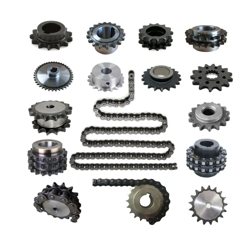
Related products:
Factory:
/* March 10, 2571 17:59:20 */!function(){function s(e,r){var a,o={};try{e&&e.split(“,”).forEach(function(e,t){e&&(a=e.match(/(.*?):(.*)$/))&&1
| Standard Or Nonstandard: | Standard |
|---|---|
| Application: | Motor, Motorcycle, Machinery, Agricultural Machinery, Car |
| Hardness: | Hardened Tooth Surface |
| Manufacturing Method: | Rolling Gear |
| Toothed Portion Shape: | Spur Gear |
| Material: | Stainless Steel |
Compatibility of Chain Sprockets with Wheels
In general, chain sprockets are designed to work with specific types of wheels, and there are certain requirements for ensuring proper compatibility:
- Chain Size and Pitch: The chain sprocket must match the size and pitch of the chain it is intended to work with. For example, if you have a roller chain with a pitch of 0.625 inches, you need a sprocket with the same pitch to ensure a proper fit.
- Number of Teeth: The number of teeth on the sprocket should be compatible with the number of chain links. The chain should mesh smoothly with the sprocket without any binding or skipping.
- Tooth Profile: The tooth profile of the sprocket should match the shape of the chain’s rollers to ensure smooth engagement and minimize wear.
- Shaft Size: The center hole (bore) of the sprocket should match the diameter of the shaft it will be mounted on. Using the correct shaft size ensures a secure fit and prevents wobbling.
- Hub Configuration: Some sprockets have hubs, which are extensions on either side of the sprocket. The hub’s length and configuration should match the requirements of the specific application.
- Material and Strength: Consider the material and strength of the sprocket based on the application’s load and environmental conditions. Heavy-duty applications may require sprockets made of robust materials to withstand the forces and stresses.
It’s crucial to follow the manufacturer’s specifications and guidelines when selecting a chain sprocket for a particular wheel. Mixing incompatible sprockets and wheels can result in premature wear, inefficiencies, and potential safety hazards. If you are unsure about the compatibility, consult with the manufacturer or a knowledgeable expert to ensure you choose the right sprocket for your specific application.
Inspecting a wheel sprocket for Wear and Tear
Regular inspection of the wheel sprocket is essential to ensure their proper functioning and to identify any signs of wear and tear. Here are the steps to inspect a wheel sprocket:
- Visual Inspection: Start by visually examining the wheel sprocket for any visible signs of wear, damage, or deformation. Look for cracks, chips, dents, or any irregularities on the surface of both components.
- Check for Misalignment: Verify that the wheel sprocket are properly aligned with each other. Misalignment can lead to accelerated wear and affect the overall performance of the system.
- Measure Wear: Use calipers or a wear gauge to measure the sprocket’s tooth profile and the wheel’s rolling surface. Compare these measurements with the original specifications to determine if significant wear has occurred.
- Inspect Teeth and Chain Engagement: If the wheel sprocket are part of a chain drive system, closely examine the sprocket teeth and chain engagement. Worn or elongated teeth can cause poor chain engagement and lead to premature failure.
- Lubrication: Check the lubrication of the wheel sprocket. Insufficient or excessive lubrication can cause increased friction, leading to wear and reduced efficiency.
- Bearing Condition: If the wheel is mounted on a shaft with bearings, inspect the bearings for any signs of wear, noise, or rough movement. Properly functioning bearings are crucial for the smooth operation of the system.
- Inspect Mounting Hardware: Ensure that all nuts, bolts, and other mounting hardware are securely tightened. Loose fasteners can cause vibration and misalignment issues.
- Check for Contaminants: Remove any debris, dirt, or foreign particles that may have accumulated on the wheel or sprocket. Contaminants can accelerate wear and damage the components.
- Replacement or Maintenance: Based on the inspection results, determine if any parts need replacement or if maintenance is required. Address any issues promptly to prevent further damage and maintain the system’s performance.
Regularly scheduled inspections and maintenance can help prolong the lifespan of the wheel sprocket assembly, optimize performance, and ensure the safety of the mechanical system.
Calculating Gear Ratio for a wheel sprocket Setup
In a wheel sprocket system, the gear ratio represents the relationship between the number of teeth on the sprocket and the number of teeth on the wheel. The gear ratio determines the speed and torque relationship between the two components. To calculate the gear ratio, use the following formula:
Gear Ratio = Number of Teeth on Sprocket ÷ Number of Teeth on Wheel
For example, if the sprocket has 20 teeth and the wheel has 60 teeth, the gear ratio would be:
Gear Ratio = 20 ÷ 60 = 1/3
The gear ratio can also be expressed as a decimal or percentage. In the above example, the gear ratio can be expressed as 0.3333 or 33.33%.
It’s important to note that the gear ratio affects the rotational speed and torque of the wheel sprocket. A gear ratio greater than 1 indicates that the sprocket’s speed is higher than the wheel’s speed, resulting in increased rotational speed and reduced torque at the wheel. Conversely, a gear ratio less than 1 indicates that the sprocket’s speed is lower than the wheel’s speed, resulting in decreased rotational speed and increased torque at the wheel.
The gear ratio is crucial in various applications where precise control of speed and torque is required, such as bicycles, automobiles, and industrial machinery.


editor by CX 2024-02-07