Product Description
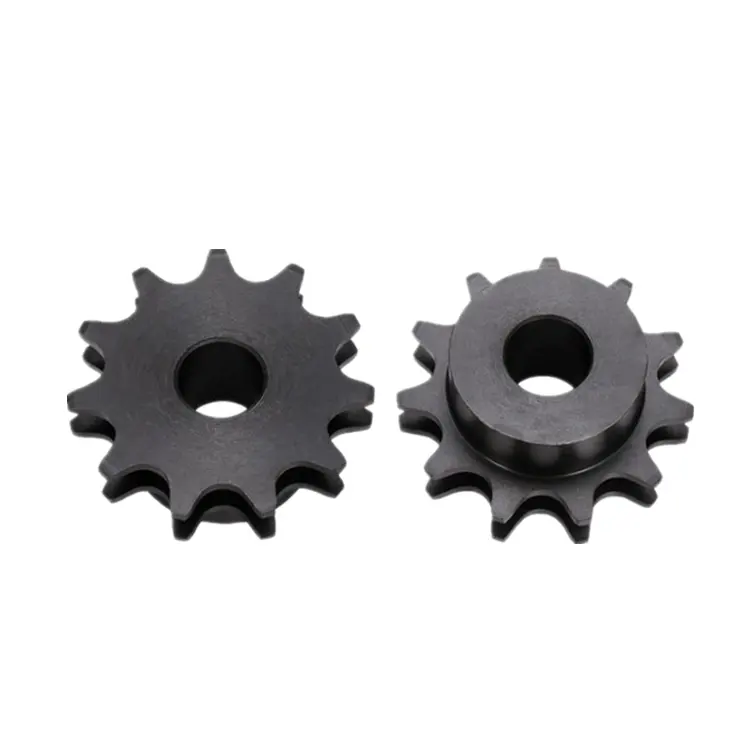
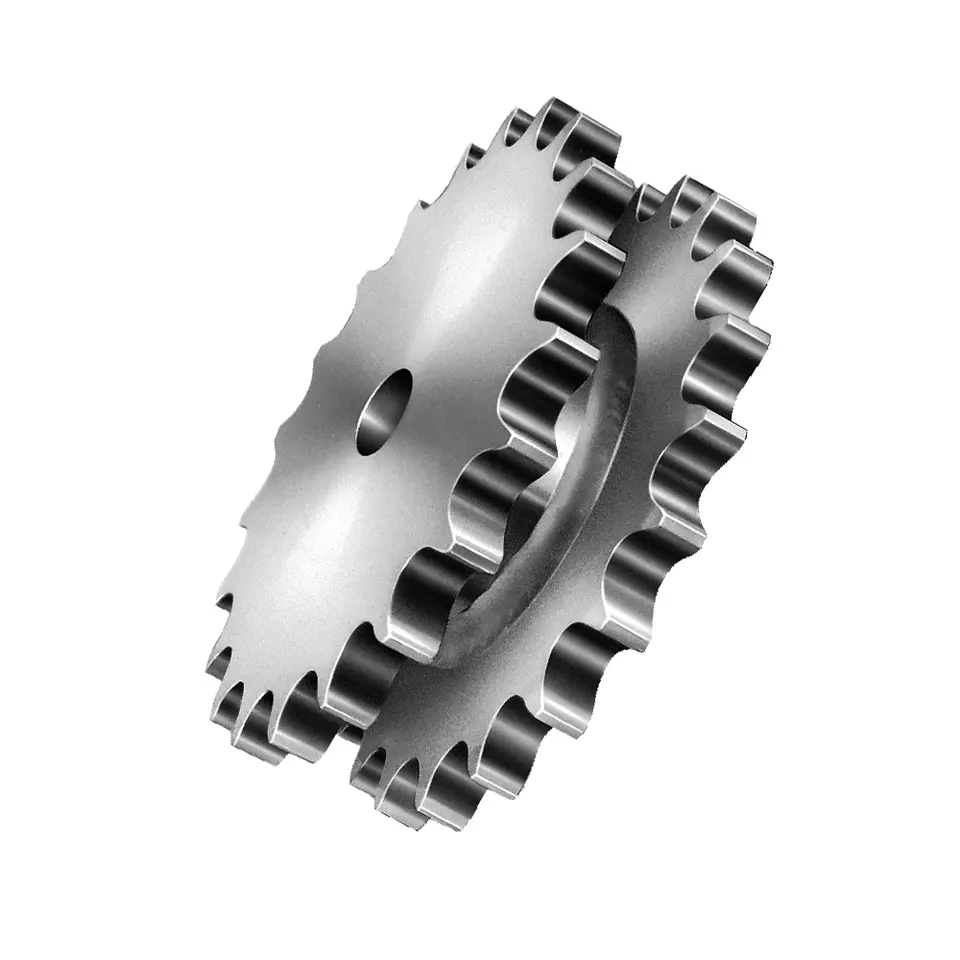
SPROCKET 1” X 17.02mm 16B SERIES SPROCKETS
| For Chain Acc.to DIN8187 ISO/R 606 | |||||
| Tooth Radius r3 | 26.0mm | ||||
| Radius Width C | 2.5mm | ||||
| Tooth Width b1 | 15.8mm | ||||
| Tooth Width B1 | 16.2mm | ||||
| Tooth Width B2 | 47.7mm | ||||
| Tooth Width B3 | 79.6mm | ||||
| 16B SERIES ROLLER CHAINS | |||||
| Pitch | 25.4 mm | ||||
| Internal Width | 17.02 mm | ||||
| Roller Diameter | 15.88mm | ||||
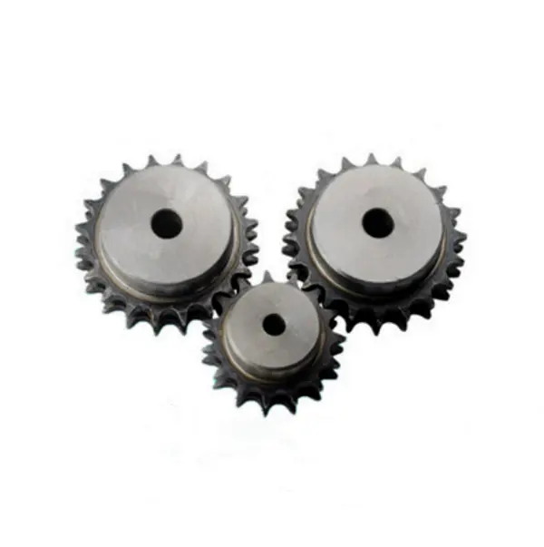
Products Show
| Z | de | dp | SIMPLEX | DUPLEX | TRIPLEX | ||||||
| dm | D1 | A | dm | D2 | A | dm | D2 | A | |||
| 8 | 77.0 | 66.37 | 42 | 16 | 35 | 42 | 16 | 65 | 42 | 20 | 95 |
| 9 | 85.0 | 74.27 | 50 | 16 | 35 | 50 | 16 | 65 | 50 | 20 | 95 |
| 10 | 93.0 | 82.19 | 55 | 16 | 35 | 56 | 16 | 65 | 56 | 20 | 95 |
| 11 | 105.1 | 90.14 | 61 | 16 | 40 | 64 | 20 | 70 | 64 | 25 | 100 |
| 12 | 109.0 | 98.14 | 69 | 16 | 40 | 72 | 20 | 70 | 72 | 25 | 100 |
| 13 | 117.0 | 106.12 | 78 | 16 | 40 | 80 | 20 | 70 | 80 | 25 | 100 |
| 14 | 125.0 | 114.15 | 84 | 16 | 40 | 88 | 20 | 70 | 88 | 25 | 100 |
| 15 | 133.0 | 122.17 | 92 | 16 | 40 | 96 | 20 | 70 | 96 | 25 | 100 |
| 16 | 141.0 | 130.20 | 100 | 20 | 45 | 104 | 20 | 70 | 104 | 25 | 100 |
| 17 | 149.0 | 138.22 | 100 | 20 | 45 | 112 | 20 | 70 | 112 | 25 | 100 |
| 18 | 157.0 | 146.28 | 100 | 20 | 45 | 120 | 20 | 70 | 120 | 25 | 100 |
| 19 | 165.2 | 154.33 | 100 | 20 | 45 | 128 | 20 | 70 | 128 | 25 | 100 |
| 20 | 173.2 | 162.38 | 100 | 20 | 45 | 130 | 20 | 70 | 130 | 25 | 100 |
| 21 | 181.2 | 170.43 | 110 | 20 | 50 | 130 | 25 | 70 | *130 | 25 | 100 |
| 22 | 189.3 | 178.48 | 110 | 20 | 50 | *130 | 25 | 70 | *130 | 25 | 100 |
| 23 | 197.5 | 186.53 | 110 | 20 | 50 | *130 | 25 | 70 | *130 | 25 | 100 |
| 24 | 205.5 | 194.59 | 110 | 20 | 50 | *130 | 25 | 70 | *130 | 25 | 100 |
| 25 | 213.5 | 202.66 | 110 | 20 | 50 | *130 | 25 | 70 | *130 | 25 | 100 |
| 26 | 221.6 | 210.72 | 120 | 20 | 50 | *130 | 25 | 70 | *130 | 30 | 100 |
| 27 | 229.6 | 218.79 | 120 | 20 | 50 | *130 | 25 | 70 | *130 | 30 | 100 |
| 28 | 237.7 | 226.85 | 120 | 20 | 50 | *130 | 25 | 70 | *130 | 30 | 100 |
| 29 | 245.8 | 234.92 | 120 | 20 | 50 | *130 | 25 | 70 | *130 | 30 | 100 |
| 30 | 254.0 | 243.00 | 120 | 20 | 50 | *130 | 25 | 70 | *130 | 30 | 100 |
| 31 | 262.0 | 251.08 | *120 | 25 | 50 | *140 | 25 | 70 | *140 | 30 | 100 |
| 32 | 270.0 | 259.13 | *120 | 25 | 50 | *140 | 25 | 70 | *140 | 30 | 100 |
| 33 | 278.5 | 267.21 | *120 | 25 | 50 | *140 | 25 | 70 | *140 | 30 | 100 |
| 34 | 287.0 | 275.28 | *120 | 25 | 50 | *140 | 25 | 70 | *140 | 30 | 100 |
| 35 | 296.2 | 283.36 | *120 | 25 | 50 | *140 | 25 | 70 | *140 | 30 | 100 |
| 36 | 304.6 | 291.44 | *120 | 25 | 50 | *140 | 25 | 70 | *140 | 30 | 100 |
| 37 | 312.6 | 299.51 | *120 | 25 | 50 | *140 | 25 | 70 | *140 | 30 | 100 |
| 38 | 320.7 | 307.59 | *120 | 25 | 50 | *140 | 25 | 70 | *140 | 30 | 100 |
| 39 | 328.8 | 315.67 | *120 | 25 | 50 | *140 | 25 | 70 | *140 | 30 | 100 |
| 40 | 336.9 | 323.75 | *120 | 25 | 50 | *140 | 25 | 70 | *140 | 30 | 100 |
| 41 | 345.0 | 331.81 | *125 | 25 | 68 | *140 | 25 | 70 | *160 | 30 | 100 |
| 42 | 353.0 | 339.89 | *125 | 25 | 68 | *140 | 25 | 70 | *160 | 30 | 100 |
| 43 | 361.1 | 347.97 | *125 | 25 | 68 | *140 | 25 | 70 | *160 | 30 | 100 |
| 44 | 369.1 | 356.05 | *125 | 25 | 68 | *140 | 25 | 70 | *160 | 30 | 100 |
| 45 | 377.1 | 364.12 | *125 | 25 | 68 | *140 | 25 | 70 | *160 | 30 | 100 |
| 46 | 385.2 | 372.20 | *125 | 25 | 68 | *140 | 25 | 70 | *160 | 30 | 100 |
| 47 | 393.2 | 380.28 | *125 | 25 | 68 | *140 | 25 | 70 | *160 | 30 | 100 |
| 48 | 401.3 | 388.36 | *125 | 25 | 68 | *140 | 25 | 70 | *160 | 30 | 100 |
| 49 | 409.3 | 396.44 | *125 | 25 | 68 | *140 | 25 | 70 | *160 | 30 | 100 |
| 50 | 417.4 | 404.52 | *125 | 25 | 68 | *140 | 25 | 70 | *160 | 30 | 100 |
| 51 | 425.5 | 412.60 | *125 | 25 | 68 | *150 | 25 | 85 | *180 | 30 | 110 |
| 52 | 433.6 | 420.68 | *125 | 25 | 68 | *150 | 25 | 85 | *180 | 30 | 110 |
| 53 | 441.7 | 428.76 | *125 | 25 | 68 | *150 | 25 | 85 | *180 | 30 | 110 |
| 54 | 448.3 | 436.84 | *125 | 25 | 68 | *150 | 25 | 85 | *180 | 30 | 110 |
| 55 | 457.9 | 444.92 | *125 | 25 | 68 | *150 | 25 | 85 | *180 | 30 | 110 |
| 56 | 466.0 | 453.01 | *125 | 25 | 68 | *150 | 25 | 85 | *180 | 30 | 110 |
| 57 | 474.0 | 461.08 | *125 | 25 | 68 | *150 | 25 | 85 | *180 | 30 | 110 |
| 58 | 482.1 | 469.16 | *133 | 25 | 68 | *150 | 25 | 85 | *180 | 30 | 110 |
| 59 | 490.2 | 477.24 | *133 | 25 | 68 | *150 | 25 | 85 | *180 | 30 | 110 |
| 60 | 498.3 | 485.23 | *133 | 25 | 68 | *150 | 25 | 85 | *180 | 30 | 110 |
| 62 | 514.5 | 501.49 | *133 | 25 | 68 | *150 | 25 | 85 | *180 | 30 | 110 |
| 64 | 530.7 | 517.65 | *140 | 25 | 68 | *160 | 25 | 90 | *180 | 30 | 110 |
| 65 | 538.8 | 525.73 | *140 | 25 | 68 | *160 | 25 | 90 | *180 | 30 | 110 |
| 66 | 546.8 | 533.80 | *140 | 25 | 68 | *160 | 25 | 90 | *180 | 30 | 110 |
| 68 | 562.9 | 549.98 | *140 | 25 | 68 | *160 | 25 | 90 | *180 | 30 | 110 |
| 70 | 579.2 | 566.15 | *140 | 25 | 68 | *160 | 25 | 90 | *180 | 30 | 110 |
| 72 | 595.4 | 582.31 | *140 | 25 | 68 | *160 | 25 | 90 | *180 | 30 | 110 |
| 75 | 619.7 | 606.56 | *140 | 25 | 68 | *160 | 25 | 90 | *180 | 30 | 110 |
| 76 | 627.0 | 614.64 | *140 | 25 | 68 | *160 | 25 | 90 | *180 | 30 | 110 |
| 78 | 643.3 | 630.81 | *140 | 25 | 68 | *160 | 25 | 90 | *180 | 30 | 110 |
| 80 | 660.0 | 646.97 | *140 | 25 | 68 | *160 | 25 | 90 | *180 | 30 | 110 |
| 85 | 699.9 | 687.39 | *140 | 25 | 78 | *160 | 25 | 90 | *180 | 30 | 110 |
| 90 | 740.3 | 727.80 | *140 | 25 | 78 | *160 | 25 | 90 | *180 | 30 | 110 |
| 95 | 781.1 | 768.22 | *140 | 25 | 78 | *160 | 25 | 90 | *180 | 30 | 110 |
| 100 | 821.1 | 808.64 | *140 | 25 | 78 | *160 | 25 | 90 | *180 | 30 | 110 |
| 110 | 902.0 | 889.48 | *140 | 25 | 78 | *160 | 25 | 90 | *180 | 30 | 110 |
| 114 | 934.3 | 921.81 | *140 | 25 | 78 | *160 | 25 | 90 | *180 | 30 | 110 |
| 120 | 982.8 | 970.32 | *140 | 25 | 78 | *160 | 25 | 90 | *180 | 30 | 110 |
| 125 | 1571.3 | 1571.73 | *140 | 25 | 78 | *160 | 25 | 90 | *180 | 30 | 110 |
Notice: *welding hub
BASIC INFO.
| Product name | DIN ISO Standard Sprocket for Roller Chain |
| Materials Available | 1. Stainless Steel: SS304, SS316, etc |
| 2. Alloy Steel: C45, 45Mn, 42CrMo, 20CrMo, etc | |
| 3. OEM according to your request | |
| Surface Treatment | Heat treatment, Quenching treatment, High frequency normalizing treatment, Polishing, Electrophoresis paint processing, Anodic oxidation treatment, etc |
| Characteristic | Fire Resistant, Oil Resistant, Heat Resistant, CZPT resistance, Oxidative resistance, Corrosion resistance, etc |
| Design criterion | ISO DIN ANSI & Customer Drawings |
| Size | Customer Drawings & ISO standard |
| Application | Industrial transmission equipment |
| Package | Wooden Case / Container and pallet, or made-to-order |
| Certificate | ISO9001: 2008 |
| Advantage | Quality first, Service first, Competitive price, Fast delivery |
| Delivery Time | 20 days for samples. 45 days for official order. |
INSTALLATION AND USING
The chain wheel, as a drive or deflection for chains, has pockets to hold the chain links with a D-profile cross section with flat side surfaces parallel to the centre plane of the chain links, and outer surfaces at right angles to the chain link centre plane. The chain links are pressed firmly against the outer surfaces and each of the side surfaces by the angled laying surfaces at the base of the pockets, and also the support surfaces of the wheel body together with the end sides of the webs formed by the leading and trailing walls of the pocket.
NOTICE
When fitting new chain spoket it is very important that a new chain is fitted at the same time, and vice versa. Using an old chain with new sprockets, or a new chain with old sprockets will cause rapid wear.
It is important if you are installing the chainwheels yourself to have the factory service manual specific to your model. Our chainwheels are made to be a direct replacement for your OEM chainwheels and as such, the installation should be performed according to your models service manual.
During use a chain will stretch (i.e. the pins will wear causing extension of the chain). Using a chain which has been stretched more than the above maximum allowance causes the chain to ride up the teeth of the sprocket. This causes damage to the tips of the chainwheels teeth, as the force transmitted by the chain is transmitted entirely through the top of the tooth, rather than the whole tooth. This results in severe wearing of the chainwheel.
FOR CHAIN STHangZhouRDS
Standards organizations (such as ANSI and ISO) maintain standards for design, dimensions, and interchangeability of transmission chains. For example, the following Table shows data from ANSI standard B29.1-2011 (Precision Power Transmission Roller Chains, Attachments, and Sprockets) developed by the American Society of Mechanical Engineers (ASME). See the references[8][9][10] for additional information.
ASME/ANSI B29.1-2011 Roller Chain Standard SizesSizePitchMaximum Roller DiameterMinimum Ultimate Tensile StrengthMeasuring Load25
| ASME/ANSI B29.1-2011 Roller Chain Standard Sizes | ||||
| Size | Pitch | Maximum Roller Diameter | Minimum Ultimate Tensile Strength | Measuring Load |
|---|---|---|---|---|
| 25 | 0.250 in (6.35 mm) | 0.130 in (3.30 mm) | 780 lb (350 kg) | 18 lb (8.2 kg) |
| 35 | 0.375 in (9.53 mm) | 0.200 in (5.08 mm) | 1,760 lb (800 kg) | 18 lb (8.2 kg) |
| 41 | 0.500 in (12.70 mm) | 0.306 in (7.77 mm) | 1,500 lb (680 kg) | 18 lb (8.2 kg) |
| 40 | 0.500 in (12.70 mm) | 0.312 in (7.92 mm) | 3,125 lb (1,417 kg) | 31 lb (14 kg) |
| 50 | 0.625 in (15.88 mm) | 0.400 in (10.16 mm) | 4,880 lb (2,210 kg) | 49 lb (22 kg) |
| 60 | 0.750 in (19.05 mm) | 0.469 in (11.91 mm) | 7,030 lb (3,190 kg) | 70 lb (32 kg) |
| 80 | 1.000 in (25.40 mm) | 0.625 in (15.88 mm) | 12,500 lb (5,700 kg) | 125 lb (57 kg) |
| 100 | 1.250 in (31.75 mm) | 0.750 in (19.05 mm) | 19,531 lb (8,859 kg) | 195 lb (88 kg) |
| 120 | 1.500 in (38.10 mm) | 0.875 in (22.23 mm) | 28,125 lb (12,757 kg) | 281 lb (127 kg) |
| 140 | 1.750 in (44.45 mm) | 1.000 in (25.40 mm) | 38,280 lb (17,360 kg) | 383 lb (174 kg) |
| 160 | 2.000 in (50.80 mm) | 1.125 in (28.58 mm) | 50,000 lb (23,000 kg) | 500 lb (230 kg) |
| 180 | 2.250 in (57.15 mm) | 1.460 in (37.08 mm) | 63,280 lb (28,700 kg) | 633 lb (287 kg) |
| 200 | 2.500 in (63.50 mm) | 1.562 in (39.67 mm) | 78,175 lb (35,460 kg) | 781 lb (354 kg) |
| 240 | 3.000 in (76.20 mm) | 1.875 in (47.63 mm) | 112,500 lb (51,000 kg) | 1,000 lb (450 kg |
For mnemonic purposes, below is another presentation of key dimensions from the same standard, expressed in fractions of an inch (which was part of the thinking behind the choice of preferred numbers in the ANSI standard):
| Pitch (inches) | Pitch expressed in eighths |
ANSI standard chain number |
Width (inches) |
|---|---|---|---|
| 1⁄4 | 2⁄8 | 25 | 1⁄8 |
| 3⁄8 | 3⁄8 | 35 | 3⁄16 |
| 1⁄2 | 4⁄8 | 41 | 1⁄4 |
| 1⁄2 | 4⁄8 | 40 | 5⁄16 |
| 5⁄8 | 5⁄8 | 50 | 3⁄8 |
| 3⁄4 | 6⁄8 | 60 | 1⁄2 |
| 1 | 8⁄8 | 80 | 5⁄8 |
Notes:
1. The pitch is the distance between roller centers. The width is the distance between the link plates (i.e. slightly more than the roller width to allow for clearance).
2. The right-hand digit of the standard denotes 0 = normal chain, 1 = lightweight chain, 5 = rollerless bushing chain.
3. The left-hand digit denotes the number of eighths of an inch that make up the pitch.
4. An “H” following the standard number denotes heavyweight chain. A hyphenated number following the standard number denotes double-strand (2), triple-strand (3), and so on. Thus 60H-3 denotes number 60 heavyweight triple-strand chain.
A typical bicycle chain (for derailleur gears) uses narrow 1⁄2-inch-pitch chain. The width of the chain is variable, and does not affect the load capacity. The more sprockets at the rear wheel (historically 3-6, nowadays 7-12 sprockets), the narrower the chain. Chains are sold according to the number of speeds they are designed to work with, for example, “10 speed chain”. Hub gear or single speed bicycles use 1/2″ x 1/8″ chains, where 1/8″ refers to the maximum thickness of a sprocket that can be used with the chain.
Typically chains with parallel shaped links have an even number of links, with each narrow link followed by a broad one. Chains built up with a uniform type of link, narrow at 1 and broad at the other end, can be made with an odd number of links, which can be an advantage to adapt to a special chainwheel-distance; on the other side such a chain tends to be not so strong.
Roller chains made using ISO standard are sometimes called as isochains.
WHY CHOOSE US
1. Reliable Quality Assurance System
2. Cutting-Edge Computer-Controlled CNC Machines
3. Bespoke Solutions from Highly Experienced Specialists
4. Customization and OEM Available for Specific Application
5. Extensive Inventory of Spare Parts and Accessories
6. Well-Developed CZPT Marketing Network
7. Efficient After-Sale Service System
The 219 sets of advanced automatic production equipment provide guarantees for high product quality. The 167 engineers and technicians with senior professional titles can design and develop products to meet the exact demands of customers, and OEM customizations are also available with us. Our sound global service network can provide customers with timely after-sales technical services.
We are not just a manufacturer and supplier, but also an industry consultant. We work pro-actively with you to offer expert advice and product recommendations in order to end up with a most cost effective product available for your specific application. The clients we serve CZPT range from end users to distributors and OEMs. Our OEM replacements can be substituted wherever necessary and suitable for both repair and new assemblies.
Q:Why choose us ?
A. we are a manufacturer, we have manufactured Chain and Sprocket for over 20 years .
B. Reliable Quality Assurance System;
C. Cutting-Edge Computer-Controlled CNC Machines;
D. Bespoke Solutions from Highly Experienced Specialists;
E. Customization and OEM Available for Specific Application;
F. Extensive Inventory of Spare Parts and Accessories;
G. Well-Developed CZPT Marketing Network;
H. Efficient After-Sale Service System
Q. what is your payment term?
A: 30% TT deposit, 70% balance T/T before shipping.
Q:Can we print our logo on your products?
A: yes, we offer OEM/ODM service, we support the customized logo, size, package,etc.
Q: Can you make chains according to my CAD drawings?
A: Yes. Besides the regular standard chains, we produce non-standard and custom-design products to meet the specific technical requirements. In reality, a sizable portion of our production capacity is assigned to make non-standard products.
Q: what is your main market?
A: North America, South America, Eastern Europe, Western Europe, Southeast Asia, Africa, Oceania, Mid East, Eastern Asia,
Q: Can I get samples from your factory?
A: Yes, Samples can be provided.
Q: If products have some quality problem, how would you deal with?
A: We will responsible for all the quality problems.
/* March 10, 2571 17:59:20 */!function(){function s(e,r){var a,o={};try{e&&e.split(“,”).forEach(function(e,t){e&&(a=e.match(/(.*?):(.*)$/))&&1
| Standard Or Nonstandard: | Nonstandard |
|---|---|
| Application: | Motor, Electric Cars, Motorcycle, Machinery, Marine, Toy, Agricultural Machinery, Car, Motor, Electric Cars, Motorcycle, Machinery |
| Hardness: | Hardened Tooth Surface |
| Samples: |
US$ 0/Piece
1 Piece(Min.Order) | Order Sample |
|---|
| Customization: |
Available
| Customized Request |
|---|
.shipping-cost-tm .tm-status-off{background: none;padding:0;color: #1470cc}
|
Shipping Cost:
Estimated freight per unit. |
about shipping cost and estimated delivery time. |
|---|
| Payment Method: |
|
|---|---|
|
Initial Payment Full Payment |
| Currency: | US$ |
|---|
| Return&refunds: | You can apply for a refund up to 30 days after receipt of the products. |
|---|
wheel sprocket System in Heavy Machinery and Industrial Equipment
Yes, a wheel sprocket system is commonly used in heavy machinery and industrial equipment for power transmission and motion control. The wheel sprocket configuration is a versatile and efficient method of transmitting rotational force between two shafts.
In heavy machinery and industrial equipment, the wheel is typically attached to one shaft, while the sprocket is mounted on another shaft. A chain or a toothed belt is wrapped around the wheel sprocket, connecting them. When the wheel is rotated, the chain or belt engages with the sprocket, causing the sprocket and the connected shaft to rotate as well. This mechanism allows the transfer of power from one shaft to the other, enabling various components and parts of the machinery to function.
Common applications of the wheel sprocket system in heavy machinery include:
- Construction Machinery: Wheel loaders, excavators, cranes, and other construction equipment often use wheel sprocket systems for efficient power transmission in various moving parts.
- Material Handling Equipment: Forklifts, conveyor systems, and other material handling equipment utilize wheel sprocket configurations to move goods and materials smoothly and reliably.
- Mining Equipment: Mining machinery, such as drilling rigs and conveyors, often incorporate wheel sprocket assemblies for power transmission in challenging environments.
- Agricultural Machinery: Tractors, combines, and other agricultural equipment use wheel sprocket systems to drive various components like wheels and harvesting mechanisms.
- Industrial Robotics: Robots and automated systems in manufacturing often utilize wheel sprocket setups for precise motion control and efficient power transmission.
One of the key advantages of the wheel sprocket system is its ability to handle heavy loads and transmit power over long distances. It is a reliable and cost-effective method of power transmission in various industrial settings. However, proper maintenance and alignment are crucial to ensuring the system’s optimal performance and longevity.
Overall, the wheel sprocket system is a widely used and effective power transmission solution in heavy machinery and industrial equipment, offering versatility and efficiency in a range of applications.
Temperature Limits for wheel sprocket System’s Operation
The temperature limits for a wheel sprocket system’s operation depend on the materials used in the construction of the components. Different materials have varying temperature tolerances, and exceeding these limits can lead to reduced performance, premature wear, and even system failure.
Here are some common materials used in wheel sprocket systems and their general temperature limits:
- Steel: Steel sprockets and wheels, which are widely used in many applications, typically have a temperature limit ranging from -40°C to 500°C (-40°F to 932°F). However, the specific temperature range may vary based on the grade of steel and any coatings or treatments applied.
- Stainless Steel: Stainless steel sprockets and wheels offer improved corrosion resistance and can withstand higher temperatures than regular steel. Their temperature limit is typically between -100°C to 600°C (-148°F to 1112°F).
- Plastics: Plastic sprockets and wheels are commonly used in low-load and low-speed applications. The temperature limit for plastic components varies widely depending on the type of plastic used. In general, it can range from -40°C to 150°C (-40°F to 302°F).
- Aluminum: Aluminum sprockets and wheels have a temperature limit of approximately -40°C to 250°C (-40°F to 482°F). They are often used in applications where weight reduction is critical.
It’s essential to consult the manufacturer’s specifications and material data sheets for the specific components used in the wheel sprocket system to determine their temperature limits accurately. Factors such as load, speed, and environmental conditions can also influence the actual temperature tolerance of the system.
When operating a wheel sprocket system near its temperature limits, regular monitoring and maintenance are necessary to ensure the components’ integrity and overall system performance. If the application involves extreme temperatures beyond the typical limits of the materials, specialized high-temperature materials or cooling measures may be required to maintain reliable operation.
Working Principle of a wheel sprocket System
In a wheel sprocket system, the sprocket is a toothed wheel that meshes with a chain or a belt to transmit rotational motion and power from one component to another. The working principle can be explained in the following steps:
1. Power Input:
The system begins with a power input source, such as an electric motor or an engine, that generates rotational motion or torque.
2. Sprocket and Chain/Belt:
The power is transferred to the sprocket, which is mounted on a shaft. The sprocket has teeth that fit into the gaps of the chain or engage with the teeth of the belt.
3. Chain/Belt Movement:
As the sprocket rotates, it pulls the chain or belt along with it due to the engagement between the teeth. This movement is transmitted to the connected component, which could be another sprocket, a wheel, or any other part of the machinery.
4. Power Output:
The rotational motion or power is then delivered to the connected component, which performs a specific function depending on the application. For example, the power could be used to drive a conveyor belt, rotate the wheels of a vehicle, or operate various industrial machines.
5. Speed and Torque:
The size of the sprocket and the number of teeth, along with the size of the chain or belt, determine the speed and torque ratio between the input and output components. Changing the size of the sprocket or using different-sized sprockets in the system can alter the speed and torque characteristics of the machinery.
6. Efficiency and Maintenance:
Efficient power transmission relies on proper alignment and tension of the chain or belt with the sprocket. Regular maintenance, such as lubrication and inspection, is essential to ensure smooth operation and prevent premature wear or damage to the system.
The wheel sprocket system is widely used in various applications, including bicycles, motorcycles, industrial machinery, agricultural equipment, and more, where efficient power transmission and motion control are required.


editor by CX 2024-01-31